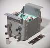
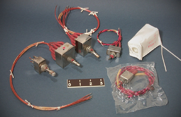
Control panel toggle switches from the Lunar Module.
Three switches at left are lever lock switches. The lever must be pulled to move the switch. Only the left-most switch
has a switch tip or cap installed.
The other two lever lock switches, and the two standard lever switches, do not have tips installed.
Flight ready switch tips were made with radioluminescent material encapsulated inside a clear plastic.
The tips radiated a small amount of light, and created a small radiation hazard. Because of the
radiation hazard the tips were installed late in the assembly sequence.
Beta cloth bag at right (in photo below) was placed behind the switch at installation to protect the rubber
at each wire connection to prevent a fire such as in the Apollo 1 accident.
Command Module designers solved the fire hazard problem using a coating on the wires.
See Panel 276.